Trace element application
This application is an expansion of the salt module and is used to model accumulation of a trace element in the soil and plant. Figure 2.8 describes the distribution of trace elements in the ecosystem as represented in the model, as well as the fluxes of tracers between different locations. Some storage pools and fluxes are the same as in the salt module, i.e. STEMin = SCl, qTEin = qClin, qTEdr = qCldr, qTEdp = qCldp. Others are specific to the trace element application, i.e. the plant storage pools (STELeaf, STEOldLeaf, STEStem, STEOldStem, STERoots, STEOldRoots and STEGrain), the soil storage pools (STESurfaceLitter, STELitter, STEHumus) and the plant uptake of trace elements (STEPlantUpt).
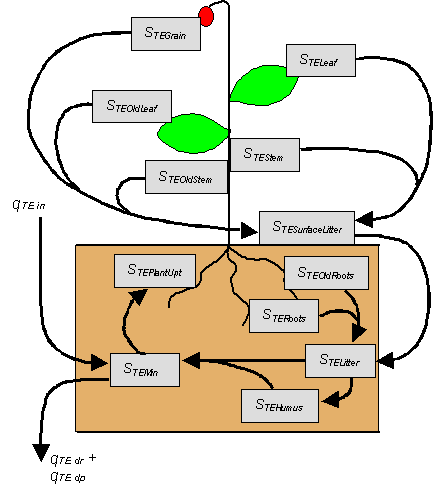
Figure 2.8. The storage and fluxes of trace elements in the model. Symbols are explained below.
Initial values, upper and lower boundary conditions, and calculations of osmotic potential (if applicable) is done in the same way in the salt application. The “mineral” trace element pool, STEMin, (i.e. the amount of dissolved trace elements in the soil plus adsorbed material) corresponds to the salt storage pool, SCl. The transport between soil layers, as well as the concentration of the trace element, is calculated in the same manner as for salt eq. (2.54). Note that the amount of adsorbed material is not calculated explicitly. All adsorbed material is considered the same, irrespective of weather it is adsorbed to mineral or to organic particles, and it should therefore not be confused with trace elements located in litter and humus.
Some additional processes are specific for the trace element application, such as plant uptake of trace elements, the allocation of trace elements in the plant and the flows of trace elements both to the soil and in the soil. These processes are described below. For detailed descriptions of plant growth or soil organic processes, please refer to the sections Plant Growth and Soil Organic Processes respectively.